Relay is a switch which controls (open and close) circuits electromechanically. The main operation of this device is to make or break contact with the help of a signal.
Provide us your requirments. Our Experts will get in touch with you shortly.
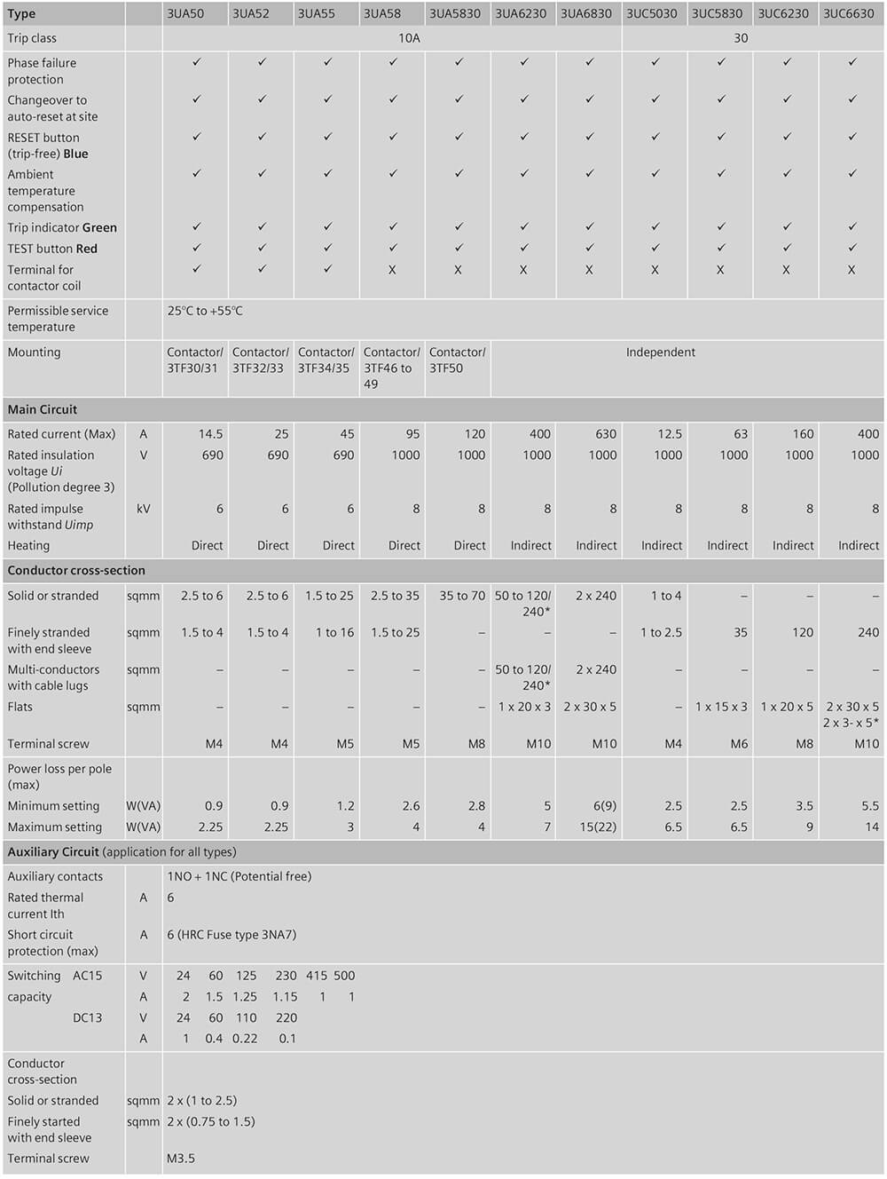
3UA overload relay: 3UA5/6 are 3 pole adjustable bi-metal overload relays mainly suitable for normal starting applications. They provide accurate and reliable protection to motors against overload as per CLASS 10A. They also offer protection against single phasing and unbalanced voltages.
3UC overload relay: 3UC5/6 are 3 pole adjustable, saturable CT operated bi-metal overload relays mainly suitable for heavy starting applications (i.e. when heavy masses are to be put in motion resulting in larger starting period). They provide accurate and reliable protection to motors against overload as per CLASS 30. They also offer protection against single phasing and unbalanced voltages.
If single-phase AC or DC loads are to be protected by the 3UA / 3UC thermal overload relays, all three bimetal strips must be heated. For this purpose, all main current paths of the relay must be connected in series.
Bimetal relays conform to IS/IEC 60947-4-1. They also carry the CE mark.
- 3UA5: 0.1 to 120A, (Class 10A, without CT)
- 3UA6: 85 to 630A, (Class 10A, CT operated)
- 3UC5/6: 2.4 to 400A (Class 30, CT operated)
Overload relay operates on the bi-metallic principle. The heater winding wound on the bimetal strips carry the current flowing through the motor. In case of overload, the current carried through the heater winding is more than the rated current. This heats up the bimetals. Due to this bi-metal strips bend and open the NC contact of the relay, which is connected in the control circuit of the contactor, thus disconnects the motor from the supply. The tripping time is inversely proportional to the current flowing through the bi-metal strips. Bi-relays are therefore, referred to as “current dependent” and inverse-time delayed relays.
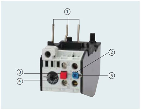
- Connection for mounting onto contactors:
Optimally adapted in electrical, mechanical and design terms to the contactors, these connecting pins can be used for direct mounting of the overload relays. Stand-alone installation is possible as an alternative (in some cases in conjunction with a stand-alone installation module). - Selector switch for manual/automatic RESET (blue):
With this switch you can choose between manual and automatic RESET. A device set to manual RESET can be reset locally by pressing the RESET button. A remote RESET is possible using the RESET modules (accessories), which are independent of size. - TEST button (red):
Trip circuit can be manually checked by using this button. During this simulation the NC contact (95-96) is opened and the NO contact (97-98) is closed. This tests whether the auxiliary circuit has been correctly connected to the overload relay. The relay must be reset with the RESET button if it has been set to manual RESET. If the thermal overload relay has been set to automatic RESET, then the overload relay is automatically reset when the TEST button is released. - Motor current setting dial:
Setting the device to the rated motor current is easy with the large rotary knob. (Recessed dial, hence no possibility of accidently change in current setting.) - Trip indicator (Green):
A separate mechanical Green Trip Indicator is provided on the front cover of the relay to indicate the tripped state of the ‘manual reset’ relay.
After tripping due to overload, the thermal overload relays require some time until the bimetal strips have cooled down. The device can only be reset after the bimetal strips have cooled down. This time (recovery time) depends on the tripping characteristics and strength of the tripping current. The recovery time allows the load to cool down after tripping due to overload.
In-built single phasing protection
In case of phase loss the current through the other two windings increases by 1.732 times the rated current of the motor. The current now flows only through the 2 bimetallic strips which should produce the required force on the tripping mechanism. This needs higher currents for longer time. As current is not too high so the relay might take higher time to trip. This can cause damage to the motor. Similar condition happens in case of phase unbalance. To take care of these conditions our birelays are constructed such that they offer a built-in single phasing protection using differential slider principle.
The temperature compensation feature reduces the effect of the ambient temperature on the tripping behavior. This ensures the minimum tripping current lies within the specified range for -25 to 55° C. For this purpose the relays are temperature compensated between service temperatures of -25° C to +55° C.
SIGUT termination Technique
- Shrouded auxiliary terminals: Increases safety, as they protect against accidental contact with live parts.
- Funnel shaped cable entries: Reduce wiring time by facilitating quick location of the connecting wire.
- Cable end-stop: They decide the insertion depth of the connective wire. As the wire cannot now protrude into the relay housing, it does not hamper the movement of the auxiliary contacts. Since the insertion depth is predetermined, insulation of the cable can be cut accordingly and the possibility of insulation getting inadvertently caught under the terminal, is avoided.
- Captive Screws: This feature prevents the screws from falling down thereby facilitates the wiring. Hence, the relays are delivered with untightened terminals. This eliminates the operation of untightening terminals before wiring.
- Lug less termination: This feature helps in reducing the termination time.
- Screw-driver guides: reduce wiring time as they allow the use of power screw-drivers.
Potential free 1NO + 1NC contact arrangement is provided as a standard feature. The 1NC contact is used in the control circuit of the contactor for disconnecting the motor in case of overload, whereas the 1NO contact can be used for various applications such as indication.
- 3UA5: suitable for direct mounting or independent mounting (with the help of independent mounting accessory)
- 3UA6 and 3UC5/6: suitable for Independent mounting.